For Enquiry
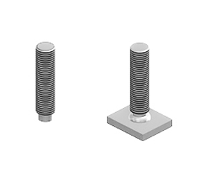
According to DIN EN ISO 13918 (Welding – Studs and ceramic ferrules for arc stud welding) welding studs for drawn arc stud welding standardly have a pressed-in aluminium ball at the welding tip. This serves as flux for improved ignition and stabilization of the electric arc as well as for deoxidizing the weld pool. (Exceptions: Insulation pins (type ISMS. ISA. ISB). bimetallic insulation pins (type VBS-MS. VBS) as well as balls do not have a pressed-in aluminium ball. Rectangular studs (type A. B and C) standardly do not have a pressed-in aluminium ball. but can be produced with aluminium ball on demand.)
For weld pool backing standardly ceramic ferrules are used. Accordingly. suitable ceramic ferrules are included in every stud shipment. A ceramic ferrule can only be used once; it is removed from the stud after welding by striking at it.
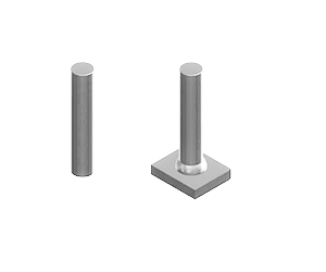
As an alternative to ceramic ferrules shielding gas can be used for weld pool backing. In this case according to DIN EN ISO 13918 welding studs without pressed-in aluminium ball at the welding tip are used.
If shielding gas is used for weld pool backing during the stud weld. welding studs without pressed-in aluminium ball at the welding tip are used (see also DIN EN ISO 13918 Welding – Studs and ceramic ferrules for arc stud welding).
Tip form 1 (standard acc. to DIN EN ISO 13918):
According to DIN EN ISO 13918 the middle part of the stud tip is d2/3 (for stud types RD. MD. PD. ID) resp. d1/3 (for stud types FD and UD). This means that the middle part of the stud tip has a small plain area (e.g. 2 mm for M6. 4 mm for M12).
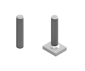
Tip form 2:
On customer request (e.g. for positioning on punch marks) we produce studs for which the middle part of the stud tip has no plain area but a sharp point.

We produce our welding studs from the following materials with excellent weldability
The material specifications conform with DIN EN ISO 13918 and DIN EN ISO 14555. For welding studs from other materials please send us your inquiry or contact us.
On demand. the material properties can be verified by an inspection document (test report. inspection certificate) according to DIN EN 10204. We are pleased to inform you about weldability to different base materials and welding parameters
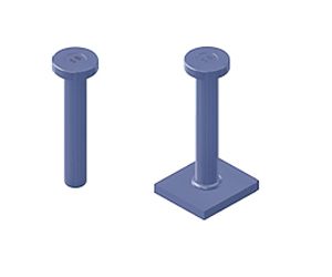
Welding studs dimensions are given in the measurement tables (all dimensions in mm). All standardized welding studs conform to DIN EN ISO 13918. Not standardized welding studs are supplied according to DIN EN ISO 13918. Special welding elements. which are not described. are delivered on request. Dimensions that are not listed in the measurement tables are delivered on request. The nominal length (l2) always corresponds to the length after welding. Depending on the diameter the length before welding (l1) is larger by a weld allowance of 1 to 5 mm.
Get an Immediate Business Quote